
Honeycomb activated carbon is widely used in industrial air purification and VOC treatment systems. Its straight channels allow air to pass through the carbon structure while providing access to adsorption surfaces.
When designing a honeycomb activated carbon filter, one common question is: How thick should the carbon bed be?
There is no single answer for every application. The appropriate bed depth depends on the airflow rate, the available filter area, the target pollutants, the desired operating period, and other practical conditions.
This article explains what bed depth means and how to evaluate it when designing or upgrading a honeycomb activated carbon adsorption system.
What Is Honeycomb Activated Carbon Bed Depth?
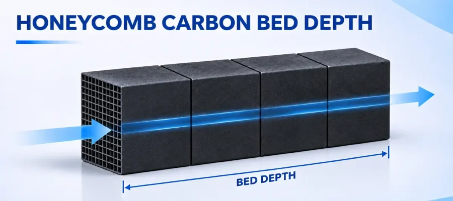
Bed depth is the total thickness of the activated carbon that air passes through in the direction of airflow.
For example, if the airflow passes through the 100 mm dimension of a honeycomb block, one layer has a bed depth of 100 mm. When two identical layers are arranged in series along the airflow path, the total bed depth is 200 mm. Three layers provide a depth of 300 mm.
| Number of Layers | Depth per Layer Along Airflow | Total Bed Depth |
|---|---|---|
| 1 layer | 100 mm | 100 mm |
| 2 layers in series | 100 mm | 200 mm |
| 3 layers in series | 100 mm | 300 mm |
These examples assume that the channels are aligned with the airflow and that each layer is 100 mm deep in the airflow direction. The actual bed depth should be calculated from the installed orientation and dimensions of the selected blocks.
Why Does Bed Depth Matter?
As air flows through the honeycomb channels, pollutant molecules can move from the air stream toward the carbon surfaces and into accessible pores. Bed depth influences the time and distance available for this process.
Under otherwise comparable conditions, a deeper bed provides a longer flow path and contains more carbon. This may improve pollutant capture and extend the operating period before the outlet concentration reaches the selected breakthrough limit.
However, adding more layers does not automatically guarantee the desired removal efficiency or service life. The result also depends on the pollutant, carbon properties, airflow distribution, and operating conditions.
Bed Depth and Empty Bed Contact Time
A useful starting point for comparing filter designs is empty bed contact time (EBCT). It is a nominal value calculated by dividing the total bed volume by the volumetric airflow rate:
EBCT (seconds) = Bed volume (m³) ÷ Airflow rate (m³/s)
For a rectangular bed, the same relationship can be expressed as:
EBCT (seconds) = Bed depth (m) ÷ Face velocity (m/s)
Face velocity is the airflow rate divided by the gross filter face area. Use the airflow rate at the operating temperature and pressure, and ensure that the units are consistent.
A Simple Calculation Example
Suppose an adsorption unit has the following operating conditions:
- Airflow rate: 3,600 m³/h, or 1 m³/s
- Gross filter face area: 1 m²
- Bed depth: 0.2 m
The face velocity is 1 m/s, and the nominal EBCT is:
0.2 m ÷ 1 m/s = 0.2 seconds
If the bed depth increases to 0.3 m while airflow and face area remain unchanged, the nominal EBCT becomes 0.3 seconds.
This calculation is a comparison tool, not a performance guarantee. EBCT treats the entire bed volume as empty. Actual gas residence time in the open channels is affected by the available flow volume and flow distribution. Adsorption also depends on how quickly different pollutants reach the carbon’s adsorption sites.
Five Factors to Consider When Selecting Bed Depth
1. Airflow Rate and Filter Face Area
A higher airflow rate through the same filter area increases face velocity and reduces nominal contact time. If the required airflow increases, the design may need a larger filter face area, a deeper bed, or a combination of both.
The available space and the fan’s operating conditions should be considered before making changes.
2. Pollutant Type and Concentration
Different VOCs and odor compounds behave differently during adsorption. Concentration, the presence of multiple compounds, and changes in the production process can all affect performance and breakthrough.
When several pollutants are present, some may compete for adsorption sites. Therefore, the bed should be evaluated against the actual gas composition rather than a single general indicator.
3. Required Removal Performance and Operating Period
A system designed to meet a strict outlet concentration or operate for a longer period between carbon replacements may require more carbon than one with less demanding targets.
Define the required outlet concentration, removal objective, operating hours, and acceptable replacement schedule early in the design process. Where possible, use representative testing or existing operating data to support the selection.
4. Pressure Drop and Fan Capacity
Increasing bed depth generally increases resistance to airflow. Pressure drop is also influenced by airflow velocity, channel geometry, gas conditions, and the condition of the installed filter.
Before adding layers, check whether the fan has sufficient pressure capacity at the required airflow. Consider the pressure drop across the complete system, including pre-filters, ducts, and other components—not only the carbon bed.
5. Temperature, Humidity, and Airborne Contaminants
Exhaust temperature and humidity can influence adsorption performance. Dust, oil mist, and sticky particles may also obstruct channels or contaminate the carbon surface.
Appropriate pre-treatment, such as particulate or oil mist removal when required, can help protect the honeycomb carbon. The pre-treatment design should match the actual exhaust conditions.
Does a Thicker Honeycomb Carbon Bed Always Perform Better?
A thicker bed can be useful, but more layers also require more installation space, carbon, and fan capacity. If the airflow is poorly distributed or the exhaust contains excessive dust or oil mist, adding carbon alone may not resolve the underlying problem.
A practical design should balance the following factors:
| Design Factor | What to Review |
|---|---|
| Airflow | Operating airflow rate and variation during production |
| Filter face area | Available installation area and resulting face velocity |
| Bed depth | Number of layers and total depth along the airflow path |
| Pollutants | Composition, concentration, and required outlet target |
| Pressure drop | Resistance across the complete system and available fan capacity |
| Operating conditions | Temperature, humidity, dust, oil mist, and operating hours |
| Maintenance | Monitoring method, replacement schedule, and access space |
What Information Should You Provide to Your Supplier?
To help evaluate a suitable honeycomb activated carbon solution, provide as much of the following information as possible:
- Application and source of the exhaust gas
- Airflow rate and operating hours
- Target pollutants and their inlet concentrations
- Required outlet concentration or removal objective
- Operating temperature and relative humidity
- Presence of dust, oil mist, or other contaminants
- Available filter face area and installation depth
- Allowable pressure drop or available fan pressure
- Expected replacement interval and existing operating data, if available
If some information is not yet available, share the details you do have. These can provide a starting point for discussing further testing and system requirements.
Find a Suitable Honeycomb Activated Carbon Solution
The right honeycomb activated carbon bed depth is determined by the complete application, not by block thickness alone. Airflow, pollutant characteristics, operating conditions, and maintenance requirements all play a role.
HANYAN provides honeycomb activated carbon for air purification and industrial exhaust treatment. Our team can review your application requirements and discuss suitable product specifications and configurations with you.
Contact HANYAN: enquiry@hanyancarbon.com
References
- U.S. Environmental Protection Agency, Monitoring by Control Technique: Activated Carbon Adsorber .
- U.S. Environmental Protection Agency, Air Pollution Control Cost Manual: Carbon Adsorbers .
Article Keywords: honeycomb activated carbon bed depth, honeycomb carbon filter design, activated carbon contact time, empty bed contact time, honeycomb carbon pressure drop, VOC adsorption system, industrial air purification, honeycomb activated carbon layers